Quite an innovative product one must say!

Friday, August 14, 2009
Foldable wing aircraft
Quite an innovative product one must say!
Draganflyer X4 Helicopter: Latest Ultra Portable, VTOL UAV

The latest UAV helicopter, the Draganflyer has been added to the UAV family . Several hundred hours of developmentH has went into its design, bringing about this sleek, sophisticated UAV. The Draganflyer X4 features much of the same technology as the earlier Draganflyer X6, but can be purchased at a fraction of the cost. Designed for commercial, government, and military applications, the Draganflyer X4 provides affordable aerial photographs and video surveillance.
Diverging from our larger 6 rotor design, the Draganflyer X4 features the same quad rotor design used by our older helicopters. Four brushless motors independently drive four carbon fiber rotor blades, all controlled by an advanced flight computer.
he flight computer uses SteadyFlight technology to process the inputs of seven individual sensors, including:
A barometric pressure sensor
Three accelerometers
Three gyroscopes
The flight computer reads sensor outputs and precisely determines the motor outputs required to keep the helicopter flying straight and level. If selected by the pilot, the barometric pressure sensor is used by the helicopter to maintain altitude. Properly trimmed and balanced, the helicopter will hold its position in the air allowing you to get excellent aerial photographs and video.
Four different cameras have been customized to work with our UAV, including:
A 12.1 MP digital still and video camera
A micro color video camera
low-light black and white video camera
A FLIR (Forward Looking Infra Red) video camera
All of these cameras transmit wireless video via a 5.8 GHz transmitter built into the mount. Wireless video can be received using either the handheld controller (which includes its own flat patch video antenna) or the optional base station. Video glasses plug directly into the handheld transmitter, allowing you to see what the helicopter is seeing and get perfectly aimed aerial photographs and video. The optional base station is compatible with any modern PC running Windows and features three standard RCA output jacks. This allows you to use your own recording equipment with the cameras or even re-transmit the video stream if needed.
Because all wireless communication is subject to interference, all of our cameras now feature a built-in DVR that records a pristine, interference-free copy of your aerial video to an SD card. After you finish flying, plug the SD card into your computer and edit the video using the software of your choice. Each camera also features a custom designed mount with a remote tilt feature. Designed to give you the best quality video possible, each camera mount features balanced, oil-filled shock absorbers. The shock absorbers keep the recorded video free from vibration, guaranteeing that you get the best possible results.
First solar-powered airplane enters the world aviation

Solar powered plane
The HB-SIA is the very first aircraft of its kind, designed to fly entirely on solar energy. In a world dominated by fossil fuels, the Solar Impulse project aims to demonstrate the potential of renewable energy as an alternative energy source for the future.designed to fly night and day without fuel or pollution.
Unveiled as the prototype of the world’s first solar-powered airplane by Bertrand Picard and André Borschberg in switzerland , Its first solar-powered flight around the world is already set to take place in 2012, making aeronautical history.
Fruit of years of work and research
The Solar Impulse HB-SIA is the result of years of research, studies, calculations and simulations. The plane boasts a wingspan of 63 meters able to carry up to 12,000 solar cells on its wings. The solar panels will power the four electric motors located in the aircraft and will charge the lithium-polymer batteries that will allow the plane to fly at night.
The HB-SIA’s mission is to check working hypotheses and to validate the selection of technologies and construction processes. If all goes according to plan the aircraft will take to the skies for a period of 36 hours next year, all without neither fuel nor pollution.
“Addressing this challenge is only possible by taking the maximum benefit of solar energy. Every watt counts, and all forms of saving energy are being looked into. Only the most sophisticated will allow it. We believe to have found them by comparing the experiences of each member of the team and by adding their potential,” said Borschberg.
The size of an airplane, the power of a scooter
The plane has the wingspan of an Airbus A340, which provides a surface for maximum solar cells. Also, the HB-SIA weighs no more than a car and has the power of a scooter. As a result, its engineers have needed to develop a completely new type of airplane with completely different characteristics.
Saturday, August 8, 2009
Emirates owns the first Airbus A380 for its airliner


 The first Airbus A380 aircraft made delivered to Emirates Airline in Hamburg, Germany. The first customer A380 powered by Engine Alliance engines, was presented to Chairman and Chief Executive Emirates Airline and Group,
Emirates unveiled its exclusive, spacious and luxurious cabin, featuring 489 seats (14 first class suites, 76 business and 399 economy). For added passenger relaxation, innovative ceiling mood lighting throughout creates a calming starry night sky effect. Fulfilling the A380 dream has required vision, innovation, a lot of courage and determination. Emirates shared in this vision early on and today the result is the world’s most modern, innovative and eco-efficient aircraft ever built. The A380 is changing the way people travel. Airbus is proud of all the engineers, staff and customers such as Emirates who have made the A380 a magnificent realityhe aircraft’s efficiency and advanced technologies result in higher operational flexibility and outstanding economics, with a range of more than 15,000 km and seat-mile costs 20 per cent lower than its closest competitor.
The A380 will take-off for the United Arab Emirates on July 29, arriving at Dubai International Airport in the afternoon. Emiratesand the first A380 commercial service is on August 1st between Dubai and New York, USA. Currently Emirates Airline has 50 Airbus aircraft in its fleet.
The A380 will take-off for the United Arab Emirates on July 29, arriving at Dubai International Airport in the afternoon. Emirates’ first A380 commercial service is on August 1st between Dubai and New York, USA. Currently Emirates Airline has 50 Airbus aircraft in its fleet.
To date, total orders and commitments for the A380 stand at 202 aircraft from 17 customers.

Wednesday, April 22, 2009
NAL successfully tests LCA O/B Elevon Box at hot wet conditions

Test setup of static strength test of Elevon box
It was a great day on friday the 17 April 2009, for the SIG group of STTD division, NAL Bangalore for successfully completed the static strength tests of LCA O/B Elevon Box at hot wet conditions
The test article tested was an Outboard Elevon box of LCA which was tested at hot wet conditions to ascertain its static strength ,before which the test box was aged for several months for moisture absorption . The Elevon box was tested for a few critical loadcases upto design limit load and finally tested for the design ultimate load for one of the most critical loadcases.
A robust test rig was designed for the testing of the elevon box which is shown in the above figure . An environmental chamber was built around the test box using high temperature polythene sheet for the circulation of steam around the box for maintaining the required temperature and humidity. The test rig and the fixtures was designed in- house in the division.
"The test article was loaded for100% DLL and was further continued to go to 150% DLL which is the design ultimate load and the test box survived that load level without any failure or amage and it was a success"said the Scientist in charge of the test Mr. M Mohan kumar .
It was observed that the strains at the critical locations monitored were well below the limits
and was not of any concern. The good thing that came out from this test was that the elevon box was able to take the ultimate loads at the aged conditions without even a small snag as the earlier experiences in testing the same elevon box at room temperature had some design issues
As an implication of these tests ,the LCA design team are assured of theLCA wing component elevon box strength capability in the worst operating conditions involving high temperatutre and humidity conditions.
Monday, April 6, 2009
A380 completes wing static test
The Airbus A380 was put through a static wing load test at the Airbus static test facility in Toulouse, France. One of the A380's wings snapped between the inbound and outbound engines at an applied pressure of about 96.67 percent of the ultimate load. Airbus vice president for engineering, Alain Garcia, felt the wing test had been a success since the rupture occurred "within 3 percent of the target." Garcia also predicted that the wing's failure will require "essentially no modifications" to production aircraft. Chief officer John Leahy recently added that the wing failure was "not a big problem at all."The ultimate load has a built in safety factor of one-and-a-half times the limit load, which is the highest aerodynamic load expected during an aircraft's lifetime of normal service. When the same test was conducted on an Airbus A330 in 1992, the wing failed just below its target load just as the A380. As American Airlines Flight 587 took off from JFK on November 12, 2001, the tail of an A300-600R had snapped off. This tragedy killed 265 people, a small number compared to the potential 853 passengers on the A380.Although not subject to operationally realistic temperature and humidity conditions, the Airbus A300 had been fully tested to ultimate load, 1.5 times the estimated limit load. Unfortunately, Airbus had clearly underestimated even the limit loads for the A300.Last fall, FedEx maintenance workers found a three-foot section of the rudder had begun to break apart on one of its Airbus jets. This discovery comes after a nearly identical Airbus lost its rudder during a flight from Cuba to Canada in early 2005. The National Transportation Safety Board (NTSB) said that the rudders of many Airbus passenger jets are made of composite plastic that appears to be dangerously prone to disintegrating. The 2001 crash and a March 25 recommendation on safety posted by the NTSB raise questions about maximum capabilities, or "limit load," of many Airbus aircraft, said Robert Spragg, an aviation lawyer in the Manhattan firm, Kreindler and Kreindler. "If there are a number of events where the limit load is exceeded, that would draw into question Airbus Industries' initial calculations," Spragg said. In a recent Airbus safety drill in Hamburg, Germany, which tested how long it would take to evacuate a fully loaded A380 with half of the exits blocked, 32 volunteers suffered minor injuries, and one man broke his leg. Airbus manager Gustav Humber said, "That was a very great success."No American carriers have so far placed orders for any A380's
North Korea tests long-range missile
 North Korea test-fired a long-range missile and five shorter-range rockets early Wednesday, but the closely watched long-range test failed within a minute, U.S. officials said.
The tests began shortly after 3:30 a.m. local time (2:30 p.m. Tuesday ET) and lasted for about five hours.
The Taepodong-2 missile, which some analysts believed capable of hitting the western United States, failed after about 40 seconds, U.S. officials said.
The U.N. Security Council planned to meet Wednesday morning to discuss North Korea's actions.
North Korean Foreign Ministry officials confirmed the tests Wednesday to reporters for two Japanese broadcasters, NHK and TV Tokyo.
U.S. National Security Adviser Stephen Hadley described the missile launches as "provocative behavior," but said they posted no immediate threat to the United States.
Washington dispatched Christopher Hill, its top negotiator in the six-party talks with the two Koreas, Japan, China and Russia, to consult with U.S. allies in Asia after the tests, Hadley said.
Hill has been the top U.S. negotiator in the six-party talks aimed at convincing North Korea to give up its nuclear weapons program.
A statement from the White House said the United States "strongly condemns" the launches and North Korea's "unwillingness to heed calls for restraint from the international community."
"We are consulting with international partners on next steps," the statement said.
"This provocative act violates a standing moratorium on missile tests to which the North had previously committed."
The United States and Japan had urged Pyongyang to stick with the moratorium on long-range missile tests it declared in 1999, after it fired a Taepodong-1 missile over Japan in 1998.
"We can now examine what the launches tell us about the intentions of North Korea," Hadley told reporters.
Washington and North Korea's Asian neighbors have been trying to convince North Korea to give up its nuclear program since 2002. Analysts called the tests an effort by North Korea to redirect attention to those talks.
"North Korea's point here is that they have capabilities, growing capabilities, and that they should be taken in a very serious way," said Wendy Sherman, a former State Department official who held talks with North Korean leader Kim Jong-Il during the Clinton administration
Indigenous Wankel Rotary Engine Takes Flight in Nishant UAV
 The first ever indigenous Wankel Rotary engine, powering Nishant, the Unmanned Air Vehicle (UAV), took off from a World War II abandoned runway near a village eight kilometres from Kolar in Karnataka. The maiden flight of the indigenous Wankel engine of a UAV, which took off yesterday morning, climbed to an altitude of 1.8 km effortlessly before cruising for 35 minutes.The air vehicle was recovered safely at the intended place at a dried-up lake after a total flight duration of 40 minutes, a defence press release said here today. The event signifies achievements in many categories: It is the first time that a Wankel engine has been developed within the country and UAV flown with an indigenous engine.The engine, a Wankel Rotary type, was a developmental project, which originated at the DRDO through VRDE, Ahmednagar, and was jointly designed and developed by NAL, a CSIR laboratory, VRDE, Ahmednagar, and ADE, Bangalore, it said. The Wankel engine is the first of its kind that was totally designed and developed in the country. Very few countries in the world have the capability to develop and master this technology, the release said.This indigenous engine is expected to replace the present imported engine for Nishant.
Sunday, April 5, 2009
SUPER PUMA (AS332 L2) HELICOPTER CRASH
At 1255 hrs UTC on Wednesday 1 April 2009 a brief Mayday call was
transmitted by the crew of a Super Puma (AS332 L2) helicopter when it was
approximately 11 nm NE of Peterhead, Scotland on a flight from BP's Miller
Oil Platform to Aberdeen. The helicopter, operated by Bond Offshore
Helicopters, carrying 2 crew and 14 passengers, was then seen to descend
rapidly and impact the surface of the sea. The weather conditions at the time
were benign. Search and rescue efforts to date have not recovered any
survivors.
The AAIB despatched a team of investigators and support staff, who arrived in
Aberdeen later on 1 April. In accordance with normal protocols, the AAIB
have invited representatives from the French accident investigation authority;
Eurocopter (the helicopter manufacturer), the European Aviation Safety
Agency and the UK Civil Aviation Authority to participate in the investigation.
Preparations are currently under way to locate and recover the combined
Voice and Flight Data Recorder and the wreckage which, after an initial
inspection, will be returned to the AAIB facilities at Farnborough for detailed
examination.
Full Scale Fatigue Testing of military aircrafts at NAL
 Full Scale fatigue testing at NAL
After successful completion of the test programme of Gnat Fighter Aircraft using full scale fatigue test rig developed by NAL, the Structural integrity Group(SIG) has taken the major task of developing a computerised full scale fatigue test rig under the project of development of fatigue test facilities. This has felt necessary in view of the practical difficulties experienced during the use of the existing six actuator full scale fatigue test rig. Sufficient clear heights for rigging of loading trees was an important consideration in the design of the new test rig. The floor area of the test rig was arrived at by examining the plan form dimensions of number of fighter air-crafts in IAF. It was decided that the test rig should be designed as a "self reacting frame work in order to avoid heavy foundation work. Another requirement was that there should be enough free entry space so that air frames of most of the fighter aircrafts can be easily moved into the test rig. The facility has been conceived Initially as a 24 actuator system in which 16 actuators are assigned to the wings, 5 actuators to the fuselage and 3 actuators to the empennage. The system will be enlarged subsequently to include more number of actuators . The test rig itself has been designed for a maximum operational load of 50,000 lbs with the maximum structural deflection restricted to 20 mm at design load
The SIG has taken up several FSFT activities for life extension of fighter aircrafts .
The recent life extension studies was done for Mig-21 Bis aircraft for IAF and all the loads experienced by the aircraft in the sevice conditions are simulated on the ground to extend its life from 2400 hrs of flying which is the designed life of MIG 21and now IAF can heave a sigh of relief - the life of the MiG-21 Bis has been enhanced. The entire fleet of the MiG-21 Bis, tests by National Aerospace Laboratories (NAL) have revealed, can now fly an additional 1,000 hours or effectively for another 10 years.
With the entire MiG-21 Bis fleet of 150 aircraft approaching its maximum life-span of 2,400 hours as per original certification by Russia, IAF went for the life-enhancement test at NAL.
It flew in a MiG-2The results come after NAL's successful completion of full-scale fatigue testing (FSFT) on the MiG-21 Bis airframe C-2090. With this a major IAF project on the total technical life enhancement (TTLE) of the MiG-21 Bis fleet has come to an end.
the aircraft had completed 2,400 hours and had no fatigue cracks. The question before IAF was - how much longer could the aircraft fly? IAF requisitioned NAL to extend MiG-21 Bis life from 2,400 hours to 4,000 hours - an additional 1,600 hours. The aircraft, however, experienced cracks and break-up after around 1,000 hours of flying.
"There was no question of further testing as the aircraft had reached its limits. But it became evident that its life could be enhanced by 1,000 flying hours," said NAL official Dr.P K Dash.
Dash further said: "What loads the aircraft experiences in flight in a whole year, we simulate on the ground in one day, checking for fatigue.
When fatigue shows up, you know that is the point up to which the aircraft can fly."The key issue in preserving structural integrity against fatigue failure, Dash said, was to get precise answers to where and when fatigue cracks would appeared in the airframe, which, if undetected in time could lead to catastrophic structural failure.
SARAS aircraft flight testing


 Flight testing of SARAS aircraft in mid air
The flight-testing expertise and resources in India have matured adequately to undertake
prototype flight-testing. The Light Transport Aircraft (LTA) program, SARAS a turboprop
aircraft being developed indigenously by National Aerospace Laboratories (NAL) of
Government of India, is the first civil aircraft program aimed at certification standard, FAR 25 . The program is unique in that the propeller configuration of SARAS is pusher type and it is
the first indigenously designed civil transport aircraft in India. In light of its unique configuration
and in absence of any precedence for certification of an indigenously designed and developed
aircraft against a FAR airworthiness standard in India, the prototype flight-testing of SARAS
aircraft becomes critical. The first flight of SARAS aircraft was flown on 29 May 2004 and the
prototype flight-testing is progressing satisfactorily.
The LTA being first aircraft being flight tested and aimed to be certified against FAR 25,
the certification agency in India was also in learning mode. The certification agency needed to
acquire adequate skills in inspection and approval leading to prototype aircraft flight-testing and
certification. The roles and responsibilities of various constituents of the flight test organization
were required to be defined. Besides, the prototype flightesting of the SARAS ac was entrusted
to Indian Air Force (IAF). Towards this, a Memorandum of Understanding was signed between
IAF and the NAL.
The flight-testing and safety structure was evolved. The flight test instrumentation, which
includes an elaborate ground telemetry station that received and displayed 328 parameters of the aircraft in real time using Pulse Code Modulation technology, was established. Experiments were conducted to improve the telemetry reception that did not restrict the test flying area. The test monitoring and direction setup was evolved. A clear hierarchy of team of system specialists that monitored parameters in real time and directed flight test point also advised the flight test crew on board the prototype aircraft
Saturday, April 4, 2009
NAL's SARAS aircraft project will not stop

The Council of Scientific and Industrial Research (CSIR) would go ahead with its project to develop the 14-seater Saras aircraft despite the crash of the second prototype of the aircraft near Bangalore on Friday last.“We will continue with the project. We will not let the sacrifice made by the three crew members of the aircraft, who belonged to the Indian Air Force’s Airbone Systems Testing Institute, to go in vain,” said CSIR Director-General Samir K. Brahmachari.He told The Hindu that the first prototype of the aircraft would be modified and converted into prototype–3 and the scientists would carry forward the various tests required for certification by the Directorate-General of Civil Aviation.Dr. Brahmachari, who visited Bangalore after the accident to take stock of the situation, said he had held discussions with the officers of the IAF and civil aviation authorities on the follow-up actions. The prototype-1 has completed around 160 test flights and the prototype-2 was on its 49th test flight when it crashed.A multi-role light transport aircraft, Saras is aimed at meeting the requirements of executive transport, air ambulance and other community services.It is designed to take off and land on short semi-prepared runways and fly up to a speed of 550 km per hour at a cruise altitude of 7.5 km.The accident came even as the Union Cabinet’s Committee on Economic Affairs recently revised the cost estimate of the CSIR’s scheme to design, develop and manufacture small civilian aircraft from Rs.96 crore to Rs.172 crore.
SARAS blackbox found and recovered at the crash site

Bangalore : A four-member DGCA team on Saturday visited the crash site, and reportedly recovered the black box from the aircraft, which could hold crucial data.After examining the aircraft, the officials took the black box for analysis. The team will visit the site again on Sunday and try to recover more equipment such as the voice recorder. Debris will also be cleared.According to defence officials, data were received at different centres of Saras PT2 just before it crashed.The telemetry at Aircraft Systems Testing Establishment of the IAF has reportedly received substantial data, but that has been sealed by the DGCA, which will follow its own procedure to decode the information.NAL wants the telemetry at its possession soon. The ATC at HAL too has received many data minutes before the crash, some of which indicated that pilots did not communicate after 3.40 pm.The DGCA has almost completed its preliminary inquiry based on which it will file a FIR
Saturday, February 21, 2009
Boeing 787 wing structural testing was a success


ALTHOUGH THE BOEING CO.'s 787 Dreamliner has been beset by a series of embarrassing delays that have now stretched more than a year and a half, engineers accomplished a significant structural milestone when they broke a 50-foot-long section of one of the composite wings.
The wing did just what it was supposed to -- withstand, with a substantial safety margin, the highest aerodynamic forces the Dreamliner is ever expected to encounter in flight.
Now, engineers and 787 program officials must decide if they want to break the wing on one of the 787 test planes. Other than first flight, it is arguably the most dramatic moment during the testing of an all-new commercial jetliner before it can carry passengers.
For a couple of years, Boeing engineers have had a lively internal debate over whether to break the wing as part of the static ground tests. The 787 can be certified without actually breaking the wing, which could damage expensive test equipment and shower part of the Everett plant with tiny shards of composite material.
Boeing released a video of the wing box being stressed until it exploded, a jagged tear ripped across the composite structure.
Before a new commercial jetliner can be certified to carry passengers, the Federal Aviation Administration requires that the wings be able to withstand loads up to 1.5 times, or 150 percent, of the highest aerodynamic load that the jet could ever be expected to encounter during flight. After holding at that load for three seconds, the test is considered successful. There is no need to keep going until the wings break. But Boeing has done so in the past, to the breaking point, to demonstrate that the wings of its jetliners have a safety margin greater than required and to validate the analytical tools that engineers use in designing new jets.Engineers previously had loaded the wing that was destroyed Saturday up to 150 percent of the limit load, but then backed off because they did not want to actually test the wing until it broke.This time they did.
Boeing would not say how much above the 150 percent threshold the wing broke, just that it was "well in excess" of that figure."The technical team doesn't feel comfortable doing that," the Boeing spokeswoman said when asked why the break-point figure was not made public. "They said that on its own, the number is meaningless and people would try to make inferences that would not be founded with the proper context."
On the Boeing video of the test, Mark Jenks, vice president of 787 development, said the break occurred in the wing box exactly where engineers predicted.The 50-foot-long wing box weighs about 55,000 pounds. Boeing and its 787 partners, Fuji Heavy Industries and Mitsubishi Heavy Industries, which manufactures the 787 wing in Nagoya, Japan, have been doing structural testing on the 787 wing box for a couple of years at Boeing's research center on East Marginal Way South across from Boeing Field.Although it is full-scale, the 50-foot piece represents only a portion of the wing section, beginning at about the center of the 787 and stopping at about two-thirds of the span of the wing.
Boeing announced the wing-test project in July 2007 at the Farnborough air show near London and said the section of wing would be stressed until it broke. At the time, however, then-787 program boss Mike Bair said there was a "raging debate" within the 787 program about whether to actually break the wings of the static test plane as part of the certification test.
Static testing involves a one-time loading of areas of the plane to determine their ability to carry load, typically the maximum load expected in the lifetime of the airframe. There is also a fatigue-test 787. Fatigue testing helps engineers determine the plane's durability and involves cyclic loading of the structure to simulate repetitive flights.
The 787 wings are composite rather than aluminum. And that has allowed them to be very long -- 197 feet from tip to tip for the 787-8. The longer wingspan reduces drag, and that makes for a more efficient plane. But it never would have been possible without composites. The lighter and stronger composite material means more of the load can be carried on the outward part of the wing.
The 787 wings are nearly as long as the wings of the much bigger 777, which Boeing engineers broke during its static-certification testing. In January 1995, the wings were bent 24 feet above their normal position before they splintered -- at 154 percent of the design load.Airbus also broke the wings of its latest jet, the A380. But they failed at only 1.45 times the limit load.
At the time the A380 wing broke, the wingtips were deflected just over 24 feet -- much farther than they could be expected to ever bend in flight. The A380 was subsequently certified by the FAA and European regulators to carry passengers, but Airbus had to make structural modifications to the wing.The 787 wings are so long that some Boeing engineers think the tips might actually touch above the plane before they snap.
Sunday, February 15, 2009
Boeing 787 changes its configuration

On January 28, 2005, the aircraft's development designation 7E7 was changed to the 787. Early released concept images depicted a radical design with highly curved surfaces. On April 26, 2005, a year after the launch of the program, the final look of the external 787 design was frozen, with a less rakish nose and a more conventional tail.
Boeing featured its first 787 in a rollout ceremony on July 8, 2007, at its Everett assembly factory, by which time it had become the fastest-selling wide body airliner in history with nearly 600 orders. Originally scheduled to enter service in May 2008, production has been delayed and it is currently scheduled to enter into service in late 2009.
When 767 sales began to go the way of the Airbus A330-200 in the late 1990s , Boeing began to consider replacement aircraft. As the 747-400 was also beginning to lose traction, the company began to consider two new projects—the Boeing Sonic Cruiser and the 747X. The Sonic Cruiser was intended to achieve higher speeds (approximately Mach 0.98) while burning fuel at the same rate as the existing 767 and A330-200 products. The 747X would stretch the 747-400 and give it a composite supercritical wing to improve efficiency
Boeing 787 uses extensive composites


When Boeing first considered extensive use of structural composites on the 787 Dreamliner, its engineers knew intuitively the epoxy/carbon fiber matrices would reduce weight significantly, allowing fuel savings and extended flying range. But after an intensive early look at composites, they realized fundamental design changes were possible that would allow functional systems integration, as well as changes in lamellar flow that would improve aerodynamics.
From a materials’ point of view, the 787 Dreamliner is one of the most revolutionary leaps in the history of manufacturing.
But in order to meet an ambitious delivery schedule – the first delivery is scheduled for May 2008 – there were tremendous hurdles to jump:
No one ever attempted to mass produce very large carbon-reinforced plastic structures, which are thermoset materials with significantly slower processing times than thermoplastics,
The critical tooling for such large sections was still very much in the development stage and, in fact, represented one of the few, small stumbles in the development program,
New coatings had to be developed to deal with the crack propagation issues, which are not a factor with aluminum. Engineers had to devise different systems to deal with electrical shorts because composites are not electrically conductive.
The Boeing 777 is 9 percent composites by weight, compared to 50 percent for the Boeing 787. Throughout the life of the 777, the Carbon-reinforced plastic materials (composites) were enhanced in terms of their properties, manufacturing and cost structure.
There are several different types of composites used on the 787, including bismaleimide, depending on specific applications requirements. There are several smaller parts made from discontinuous fibers that can be molded into odd shapes. There is also extensive use of thermoplastics in the interior of the aircraft, but that’s not a departure from previous designs.
All of the composites are supplied by Toray Industries, the world’s largest producer of carbon fiber. Since 2004, Boeing has placed composites orders with Toray estimated at more than $6 billion, creating pressure on prices and supplies for other users. The estimate was based on projected production as of 2006, numbers which are already out-of-date because of the spectacular success of the 787.
Composites aren’t the only materials’ news in the 787 Dreamliner. While composites represent 50 percent by weight (80 percent by volume) of the Dreamliner structure, other materials represented are aluminum, 20 percent; titanium, 15 percent; steel, 10 percent and 5 percent, other. Most notable among the “other” is the first-time widespread use in aircraft structures of plastic heat sinks. That’s right – plastic heat sinks. Plastics that are highly loaded with heat-removing materials such as carbon or ceramics have been around for a while, but have not yet penetrated the aircraft market. Their great advantage is their ability to be molded into net shapes. The economics for plastics can be favorable depending on total tooling and finishing costs. They can be designed with additional surface areas as fins and ribs to improve convective heat transfer. Costs and properties can be balanced depending on which engineering thermoplastics are used. For example, nylon can improve economics while liquid crystal polymer can improve properties. They are typically loaded 30 to 40 percent with thermally conductive materials.
Airbus a380 wing Static testing

Airbus is downplaying test results in which an A380 wing undergoing static testing failed slightly before the required design limit.
The wings are supposed to take 1.5 times the design load limit but this one failed at 1.45 times, about 3.3 percent shy of the certification requirement.
Airbus spokeswoman Barbara Kracht said the wing will need some “refinements” but the aircraft is on schedule for certification and first deliveries late this year. “We will need to find out from the data what is really needed but it’s certainly not a redesign of the wing,” Kracht told Associated Press.
In order for an aircraft to be certified here in the U.S., it must withstand the maximum “g” loading specified for that category, plus a 50% overload factor. For example, in the Normal category, the aircraft must withstand a positive load of 3.8g and a negative load of -1.52g at maximum gross weight. It must also be able to withstand an additional 50% of those loads without failing.
These “static” tests, as they’re called, are accomplished on the ground by mechanically loading up the wings. Sometimes this is done by simply placing sandbags on the wings to simulate a load. Large manufacturers like Boeing and Airbus use slightly more expensive methods. I’ve seen video of a 777 wing being tested to failure — the wings bent up to the point where they almost touched. In other words, it handled far more than the required loading.
The requirements for the Transport category are set out in 14 CFR 25.337(b)-(d):
(b) The positive limit maneuvering load factor n for any speed up to Vn may not be less than 2.1+24,000/ (W +10,000) except that n may not be less than 2.5 and need not be greater than 3.8 — where W is the design maximum takeoff weight.
(c) The negative limit maneuvering load factor –
(1) May not be less than −1.0 at speeds up to VC; and
(2) Must vary linearly with speed from the value at VC to zero at VD.
(d) Maneuvering load factors lower than those specified in this section may be used if the airplane has design features that make it impossible to exceed these values in flight.
So if the plane is going to be certified in the Transport category, it will have to handle somewhere between 2.5 and 3.8 positive G — plus 50% — depending on the maximum takeoff weight.
I’ve never heard of an aircraft failing to withstand the 1.5x test. That’s not to say it’s never happened, just that I’m not familar with such an ocurrance.
However you slice it, this has got to be a huge embarrassment for Airbus. Even if the flaw was simply a construction defect in the prototype, it will bring into question every other aspect of the A380’s design and construction in the minds of potential customers, not to mention the flying public.
Sunday, January 25, 2009
Theory of Flight
Four forces acting on an aircraft in flight.
 The three Axis of Rotation
 Control Surfaces
 a. Aircraft. Any weight-carrying device designed to be supported by air, either by buoyancy or by aerodynamic reaction.
b. Airfoil. A surface so designed as to produce an aerodynamic
reaction to its direction of motion.
c. Airspeed. Speed of the aircraft in relation to the surrounding air.
d. Angle of Attack. The angle between the relative air flow and the chord of the airfoil.
e. Angle of Incidence. The angle formed between the chord and the longitudinal datum line.
f. Aspect Ratio. The ratio between the span and the chord.
g. Camber. The curvature of the wing.
h. Centre of Gravity. The balance point.The point through which all weight acts downwards.
j. Centre of Pressure. The point along the airfoil chord of the body axis through which the resultant aerodynamic force acts.
k. Chord. An imaginary line from the leading edge to the trailing edge of an airfoil.
m. Dihedral. The angle each wing makes with the horizontal.
n. Drag. The total resistance to the aircraft in flight.
p. Equilibrium. Balance between forces, when opposing forces are equal.
q. Fin. Vertical stabilizer.
r. Groundspeed. The relation between the speed of the aircraft and a point on the ground.
s. Lateral Axis. An imaginary line running from wing tip to wing tip through the centre of gravity.
t. Longitudinal Axis. An imaginary line extending through the fuselage from the nose to the tail.
u. Mainplane. Main supporting airfoil (wing) of the aircraft.
v. Pitching. Movement around the lateral axis.
w. Rolling. Movement around the longitudinal axis.
x. Span. Measurement from wing tip to wing tip.
y. Stable. An object is stable if, when disturbed, it returns to its original position.
z. Stabilizer. Any surface of airfoil shape whose primary function is to correct instability of an aircraft in flight.
aa. Stalling Angle. The angle of attack of an airfoil where the smooth airflow breaks away and becomes turbulent.
ab. Sweepback. Outward and backward angle of the leading edge of the mainplane.
ac. Tailplane. Horizontal stabilizer.
ad. Turbulence. Disturbed air flow.
ae. Unstable. An object is unstable if, when disturbed, it continues to move farther and farther from its original position.
af. Venturi. A variable section tube wider at each end than in the middle.
ag. Vertical Axis. An imaginary line running at right angles to the longitudinal and lateral axes through the centre of gravity.
ah. Wing Tip Vortices. Spiralling air at the wing tips caused by high-pressure air from the lower surface of the airfoil moving into the low-pressure air on top of the airfoil.
ak. Yawing. Movement around the vertical axis.
What makes airplane fly?
Almost everyone today has flown in an airplane. Many ask the simple question "what makes an airplane fly?" The answer one frequently gets is misleading and often just plain wrong. We hope that the answers provided here will clarify many misconceptions about lift and that you will adopt our explanation when explaining lift to others. We are going to show you that lift is easier to understand if one starts with Newton’s laws rather than the Bernoulli principle. We will also show you that the popular explanation that most of us were taught is misleading at best and that lift is due to the wing diverting air down. Most of this diverted air is pulled down from above the wing.
Let us start by defining three descriptions of lift commonly used in textbooks and training manuals. The first we will call the Mathematical Aerodynamics Description of lift, which is used by aeronautical engineers. This description uses complex mathematics and/or computer simulations to calculate the lift of a wing. It often uses a mathematical concept called "circulation" to calculate the acceleration of the air over the wing. Circulation is a measure of the apparent rotation of the air around the wing. While useful for calculations of lift, this description does not lend themselves to an intuitive understanding of flight.
The second description we will call the Popular Description, which is based on the Bernoulli principle. The primary advantage of this description is that it is easy to understand and has been taught for many years. Because of its simplicity, it is used to describe lift in most flight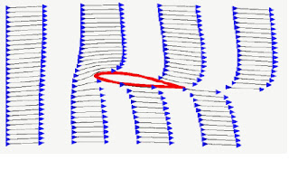 training manuals. The major disadvantage is that it relies on the "principle of equal transit times", or at least on the assumption that because the air must travel farther over the top of the wing it must go faster. This description focuses on the shape of the wing and prevents one from understanding such important phenomena as inverted flight, power, ground effect, and the dependence of lift on the angle of attack of the wing.
Let us start by defining three descriptions of lift commonly used in textbooks and training manuals. The first we will call the Mathematical Aerodynamics Description of lift, which is used by aeronautical engineers. This description uses complex mathematics and/or computer simulations to calculate the lift of a wing. It often uses a mathematical concept called "circulation" to calculate the acceleration of the air over the wing. Circulation is a measure of the apparent rotation of the air around the wing. While useful for calculations of lift, this description does not lend themselves to an intuitive understanding of flight.
The second description we will call the Popular Description, which is based on the Bernoulli principle. The primary advantage of this description is that it is easy to understand and has been taught for many years. Because of its simplicity, it is used to describe lift in most flight
 training manuals. The major disadvantage is that it relies on the "principle of equal transit times", or at least on the assumption that because the air must travel farther over the top of the wing it must go faster. This description focuses on the shape of the wing and prevents one from understanding such important phenomena as inverted flight, power, ground effect, and the dependence of lift on the angle of attack of the wing.
The third description, which we are advocating here, we will call the Physical Description of lift. This description of lift is based primarily on Newton's three laws and a phenomenon called the Coanda effect. This description is uniquely useful for understanding the phenomena associated with flight. It is useful for an accurate understanding the relationships in flight, such as how power increases with load or how the stall speed increases with altitude. It is also a useful tool for making rough estimates ("back-of-the-envelope calculations") of lift. The Physical Description of lift is also of great use to a pilot who needs an intuitive understanding of how to fly the airplane.
Subscribe to:
Posts (Atom)